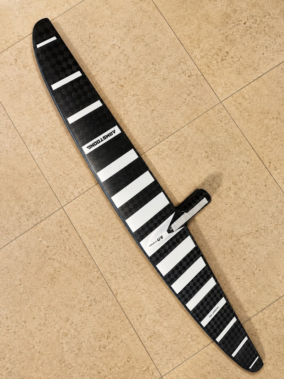


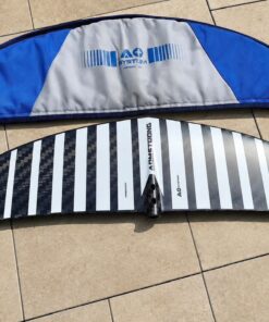
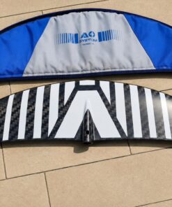
Used Armstrong Foil V2 HA 680


€500.00
Product Description
The Used Armstrong Foil V2 HA 680 is a compact high-aspect hydrofoil front wing intended for riders seeking a combination of speed, efficient glide, responsive turning, and surprisingly usable low-speed lift for its relatively small 680cm² surface area. Armstrong’s current official HA range includes the HA680, specified at 680cm² area, 828mm span, and 10.0 aspect ratio.
Armstrong describes the HA design as combining low-speed lift with high-speed stability, efficient glide, and fluid turning. Its foil section is intended to generate useful low-end lift for its size, while a trailing-edge reflex contributes to active pitch stability. The current HA family is designed for use across surf, wing, and downwind foiling rather than being limited to one discipline.
One naming point deserves clarification: Armstrong’s current official product page identifies the size simply as HA680 rather than “V2 HA 680.” Therefore, if “V2” appears in a used listing, it should be treated as seller or generation terminology unless documentation for the specific foil confirms that designation.
Used Armstrong Foil V2 HA 680 – High Aspect Front Foil Technical Overview
High-Aspect Design, HA680 Specifications, Glide, Lift, Stability, Armstrong System Compatibility, and Related Foiling Terminology
HA Front Foil
The HA Front Foil family is Armstrong’s high-aspect range designed around efficient glide, low-speed lift, high-speed control, and responsive maneuverability. Armstrong positions the HA family for surf, wing, and downwind use, giving the design broader versatility than a foil optimized for only one discipline.
HA680 Engineering
The HA680 has an official area of 680cm², span of 828mm, and aspect ratio of 10.0. Those figures place it toward the smaller, faster, more performance-oriented portion of the HA range.
High Aspect Ratio
An aspect ratio of 10.0 means the wing combines relatively long span with modest surface area.
In practical hydrodynamic terms, that geometry is associated with reduced induced drag and efficient glide compared with lower-aspect wings of similar area.
However, actual behavior also depends on section profile, outline, stabilizer, mast stiffness, rider weight, and conditions.
Low-Speed Lift
Armstrong specifically emphasizes that the HA foil section produces unusually strong low-end lift for its size. That allows riders to use a smaller front foil while retaining a useful lower-speed range.
High-Speed Stability
High-aspect foils can become sensitive in pitch if poorly designed.
Armstrong addresses this through a trailing-edge reflex feature that the company says produces active pitch stability and improved control at higher speeds.
Hydrofoil Lift Stability
The phrase hydrofoil lift stability describes how predictably a foil maintains vertical lift as speed, pitch angle, water texture, and rider input change.
On this platform, lift stability is influenced by the front foil section, trailing-edge reflex, stabilizer selection, mast stiffness, fuselage geometry, and rider technique. Armstrong specifically identifies trailing-edge reflex as a major contributor to pitch stability in the HA design.
Front Foil
A front foil is the primary underwater lifting surface in a hydrofoil system.
It provides most of the hydrodynamic lift while the stabilizer contributes pitch control and balance.
The HA680 is the front foil component rather than a complete hydrofoil setup.
Hydrofoil Front Wing
The phrase hydrofoil front wing refers to the same principal lifting component.
Area, span, aspect ratio, foil-section profile, and outline shape all influence how the foil takes off, glides, accelerates, and turns.
Wing Foil Front Wing
As a wing foil front wing, the HA680 can be used with an inflatable wing above the water while the hydrofoil supplies lift below.
Its smaller surface area and relatively high aspect ratio generally make it more suited to riders who already have enough technique, wind, or board efficiency to access its performance range.
Armstrong Foils
armstrong foils refers to the manufacturer’s broader hydrofoil ecosystem, including front foils, stabilizers, masts, fuselages, boards, and wings.
The HA family is part of Armstrong’s current front-foil lineup.
Armstrong Foiling
The phrase armstrong foiling encompasses wing foiling, surf foiling, downwind foiling, and related hydrofoil disciplines using Armstrong components.
The current HA family is officially positioned for surf, wing, and downwind foiling.
Armstrong Fuselage
The armstrong fuselage connects the front foil to the mast and stabilizer.
Within Armstrong’s current A+ assembly architecture, the mast, fuselage, front foil, and stabilizer are designed to join together as a rigid system.
A+ System
Armstrong describes the A+ System as its proprietary foil assembly architecture linking the mast, fuselage, front foil, and stabilizer to create a solid, smooth feel on the water.
For a used front foil, compatibility with the owner’s exact mast and fuselage generation should therefore be confirmed before installation.
Armstrong Performance Mast
An armstrong performance mast is intended to provide a stiff and efficient connection between board and foil.
Mast stiffness becomes increasingly important with smaller, faster front foils because unwanted flex can reduce precision and make high-speed handling feel less direct.
Armstrong Integrated Foil Masts Price
The phrase armstrong integrated foil masts price concerns the cost of mast hardware rather than HA680 performance.
A mast is a separate component and should not be assumed to be included with a used front foil unless the listing explicitly says so.
Armstrong Integrated Foil Masts Price 2025
Likewise, armstrong integrated foil masts price 2025 refers to historical pricing information rather than an engineering specification.
Current price information can change, whereas front-foil dimensions such as 680cm², 828mm, and 10.0 aspect ratio are defined technical characteristics of the HA680.
Armstrong Foil Board
An armstrong foil board provides the platform above the water.
Board length, volume, width, bottom shape, and track position all affect takeoff and control.
A front foil as small as the HA680 may feel substantially easier to access when paired with an efficient board than with a short, low-volume board.
Armstrong Foil Boards
armstrong foil boards cover several disciplines and riding styles.
The correct board for this foil depends on rider weight, wind or swell power, experience level, and the desired balance between takeoff ease and maneuverability.
Foiling Board
A foiling board is designed to transition efficiently from displacement or planing on the water to hydrofoil flight.
Board efficiency can be particularly important with smaller high-aspect front foils because sufficient initial speed is needed before the foil generates full lift.
Foiling Boards
The broader phrase foiling boards includes compact wing boards, prone surf boards, midlength boards, and long downwind designs.
Each board type changes how quickly a rider can generate the speed needed to engage a front foil.
Surf Foil Board
A surf foil board typically prioritizes paddle-in ability, compact control, and wave performance.
The HA680 may suit more experienced surf foilers where speed, glide, and turning efficiency are prioritized over very early lift.
Surf Foilboard
The term surf foilboard refers to the same general category.
Board volume and paddle efficiency should be matched to the rider rather than selected from front-foil area alone.
Surf Foil Boards
surf foil boards vary greatly in volume, length, and intended wave size.
The same front foil can feel substantially different depending on whether it is mounted under a compact prone board or a longer, more glide-oriented board.
Surf Foil
The phrase surf foil describes foil riding powered primarily by wave or swell energy rather than an inflatable wing.
Armstrong specifically lists surf foiling among the intended disciplines for its HA family.
Armstrong Downwind Board
An armstrong downwind board is typically longer and narrower than a compact wing board, helping generate water speed before takeoff.
That extra glide can make smaller efficient foils more accessible in lower-energy conditions.
Armstrong Downwind Boards
armstrong downwind boards are designed around efficient acceleration, water release, and sustained glide before foil flight.
This can complement the HA family’s emphasis on glide once airborne.
Armstrong Downwind Foil
The phrase armstrong downwind foil refers to efficient foil configurations designed to connect swell energy over distance.
Armstrong lists downwind use among the intended applications for the current HA family.
Armstrong Downwind Foil Board
An armstrong downwind foil board combines a long, efficient board shape with hydrofoil mounting capability.
Such a board can help generate the initial speed needed for smaller high-aspect front foils.
Armstrong V1 Downwind Board
The phrase armstrong v1 downwind board refers to an earlier board generation and should not be treated as a specification of the HA680 itself.
Armstrong Midlength
armstrong midlength refers to the category of longer, efficient boards positioned between compact wing boards and full downwind designs.
Midlength architecture can improve glide and early acceleration without requiring the extreme length of a dedicated downwind board.
Armstrong Mid Length Board
The phrase armstrong mid length board refers to the same general concept.
Pairing a smaller foil with a more efficient board can broaden the conditions in which the foil becomes practical.
Foil for SUP
The phrase foil for sup refers to hydrofoils used with stand-up paddle setups.
Suitability depends on rider weight, paddle technique, board dimensions, swell energy, and the desired lift characteristics.
Armstrong Wing
An armstrong wing is the handheld inflatable aerodynamic wing used above the water during wing foiling.
It provides forward power while the hydrofoil converts water speed into lift.
Armstrong Wings
armstrong wings include different sizes and performance categories.
Wing size should be matched to rider weight, wind strength, and the amount of lift required to get a smaller front foil such as the HA680 flying.
Armstrong Wing Foil
The phrase armstrong wing foil describes using an Armstrong wing with a compatible board and hydrofoil setup.
The HA680’s efficient high-aspect architecture can suit powered wing sessions where speed, glide, and responsive control are priorities.
Kite Armstrong
The phrase kite armstrong is broad search terminology and does not define a specific engineering feature of this front foil.
The current official HA product information focuses on surf, wing, and downwind foiling applications.
HA Front Foil for Sale
The phrase HA Front Foil for sale concerns commercial availability.
For a used HA680, actual physical condition should be evaluated alongside model specifications before value is assessed.
Armstrong Foils for Sale
Likewise, armstrong foils for sale describes availability rather than performance.
Used condition can vary greatly between examples even when they share identical factory specifications.
Used Foil Condition
A used carbon front foil should be inspected carefully before use.
Pay particular attention to leading-edge chips, trailing-edge damage, deep scratches, carbon cracks, impact marks, mounting-hole condition, barrel-nut area, and evidence of previous structural repairs.
Minor cosmetic scratches are very different from cracks or delamination.
Leading-Edge Condition
The leading edge directly interacts with water flow.
Small surface marks may be primarily cosmetic, whereas significant chips or irregular repairs can disturb hydrodynamic flow and potentially affect performance.
Trailing-Edge Condition
The trailing edge is comparatively thin and can be damaged during transportation or accidental contact.
Check for chips, cracking, separation, or poorly finished repairs.
Carbon Construction Condition
Carbon components are valued for stiffness and low weight but should be inspected after significant impacts.
Damage may present as cracking, crushed laminate, delamination, or unusual flexibility.
Any suspected structural damage deserves professional assessment before water use.
Mounting Interface Condition
The attachment area between front foil and fuselage should remain clean and structurally sound.
The current Armstrong HA is part of the A+ assembly architecture and includes specific mounting hardware with the factory package.
A used example may or may not include all original screws or barrel hardware.
Protective Cover
Armstrong currently includes a protective cover with new HA front foils.
For a used foil, a cover is valuable because it protects both the thin trailing edge and surrounding equipment during transportation.
Glide Performance
Glide is a defining characteristic of the HA design.
Armstrong states that the foil section provides both early lift and efficient glide, while the overall shape remains maneuverable enough for surf, wing, and downwind riding.
Pumping Efficiency
High-aspect geometry can support efficient pumping because reduced induced drag helps preserve forward momentum between rider inputs.
Actual pumping performance also depends on stabilizer setup, mast drag, rider timing, and overall foil weight.
Turning Character
High-aspect designs are sometimes associated primarily with straight-line glide, but Armstrong specifically emphasizes flowing turns and maneuverability in the HA family.
The smaller 680cm² size should generally feel quicker and more responsive than larger members of the same range, though it also requires greater speed to support heavier riders.
Active Pitch Stability
Trailing-edge reflex is one of the more technically important features of the HA design.
Armstrong says this provides active pitch stability, improving control authority at speed and during maneuvers.
Speed Range
A small 680cm² high-aspect foil is fundamentally oriented toward efficiency and speed rather than maximum low-speed buoyant lift.
However, Armstrong’s foil-section design is specifically intended to retain a useful low-speed range relative to its size.
Rider Skill Considerations
The HA680 will generally make more sense for experienced riders than very large beginner-oriented foils.
Smaller area means the rider needs adequate speed and control to maintain lift.
Board efficiency, mast height, stabilizer choice, water state, and body weight all affect how demanding the foil feels.
Why the HA680 Size Matters
At 680cm², the foil offers a compact surface area while retaining an 828mm span and 10.0 aspect ratio.
That combination creates a performance profile centered on efficient glide, speed, and responsive control rather than maximum early lift.
Why Aspect Ratio Matters
Aspect ratio helps describe the relationship between span and area.
A higher ratio generally reduces induced drag and improves glide efficiency, although outline, section shape, and twist remain equally important to real-world handling.
Why Trailing-Edge Reflex Matters
Armstrong specifically uses trailing-edge reflex to increase pitch stability in the HA family.
That feature helps explain why the foil can maintain high-aspect efficiency without becoming excessively sensitive in pitch.
Why Used Condition Matters
The hydrodynamic performance of a used front foil depends on the condition of its surfaces and structure.
A clean foil with minor cosmetic marks may perform close to original specification, while deep leading-edge damage, carbon cracking, poor repairs, or distorted mounting surfaces can substantially change both performance and reliability.
Overall Technical Perspective
The Used Armstrong Foil V2 HA 680 is best understood through the current HA680 specification: 680cm² surface area, 828mm span, and 10.0 aspect ratio, combined with Armstrong’s high-aspect foil section, trailing-edge reflex, and A+ assembly architecture.
Its principal strengths are efficient glide, relatively early lift for its compact size, high-speed stability, pumping efficiency, and versatile surf, wing, and downwind application. For a used example, however, carbon integrity, leading- and trailing-edge condition, mounting surfaces, hardware, and previous repairs ultimately determine how closely the foil retains its intended performance.
Hydrodynamic Performance, Glide Efficiency, Speed Control, Turning Response, Stability, and Real-World Foiling Characteristics
The performance of a compact high-aspect front wing depends on much more than surface area alone. Span, aspect ratio, foil-section geometry, stiffness, stabilizer selection, mast characteristics, board efficiency, rider weight, and water conditions all influence the final experience. With a relatively small lifting surface, the design places particular emphasis on maintaining momentum, reducing unnecessary drag, and delivering controlled performance across a broad speed range. For a used example, surface and structural condition become equally important because damage to critical areas can change how smoothly water flows around the foil.
Overall Performance Character
The overall character is oriented toward riders who value efficiency, speed, glide, and responsive handling.
Rather than depending on a very large lifting surface, the design uses efficient hydrodynamic geometry to produce useful lift while keeping drag relatively low.
Consequently, the experience can feel considerably more dynamic than that of a much larger, slower front wing.
Understanding High-Aspect Efficiency
A high-aspect planform combines relatively long span with comparatively modest surface area.
This arrangement can reduce induced drag and improve the distance traveled while preserving momentum.
However, aspect ratio should never be considered independently because section profile and outline shape remain fundamental to overall behavior.
Initial Lift Characteristics
Before foil flight begins, sufficient forward water speed must be developed.
A smaller front wing generally requires more speed than a substantially larger design.
Therefore, efficient board acceleration, rider technique, wind or wave energy, and body weight strongly influence how easily takeoff occurs.
Low-Speed Control
Good low-speed behavior is particularly valuable in a performance-oriented design.
As speed decreases, available hydrodynamic lift also changes.
Predictable behavior near the lower end of the usable range can make transitions between powered movement and slower maneuvering easier to manage.
Acceleration
Once sufficient speed develops, reduced drag becomes increasingly noticeable.
Efficient underwater geometry allows the system to preserve more forward momentum rather than losing excessive energy to resistance.
This can create a smooth transition from moderate cruising speeds into faster riding.
High-Speed Behavior
At higher speeds, stability becomes increasingly important.
Small changes in rider position can create noticeable changes in pitch and lift.
A well-designed system should therefore combine efficiency with enough predictability to prevent the foil from feeling excessively nervous.
Pitch Stability
Pitch describes rotational movement around the lateral axis.
Stable pitch behavior helps the rider maintain consistent ride height as speed and loading change.
The stabilizer, fuselage, mast stiffness, front-wing geometry, and rider stance all contribute to this characteristic.
Roll Response
Roll determines how readily the foil banks from one side to the other.
A wider span can increase leverage, while refined geometry can preserve maneuverability.
The resulting feel depends heavily on speed and rider input.
Yaw Control
Yaw refers to rotation around the vertical axis.
Predictable yaw behavior contributes to smooth directional control and clean transitions.
Excessive flex or damaged mounting interfaces can negatively influence the direct connection between rider input and underwater response.
Turning Characteristics
Turning performance depends on more than front-wing dimensions.
Bank angle, speed, stabilizer setup, fuselage characteristics, mast stiffness, and rider technique all influence the radius and feel of a turn.
A smaller surface area can contribute to a more responsive character when adequate speed is maintained.
Carving Performance
Carving requires the foil to maintain controlled lift while banking through a turn.
Efficient geometry can help preserve momentum throughout the arc.
Smooth rider input generally produces better results than abrupt changes in pressure.
Glide Efficiency
Glide describes the ability to continue traveling efficiently when external power temporarily decreases.
Reduced drag becomes particularly valuable during swell connection, transitions, and periods when aerodynamic input is reduced.
A clean hydrodynamic surface helps preserve this efficiency.
Momentum Retention
Momentum retention is closely connected to glide.
Once moving efficiently, a low-drag system can carry speed farther between rider inputs.
This characteristic becomes especially useful when linking separate sections of moving water.
Pumping Characteristics
Pumping uses coordinated body movement to maintain or generate foil speed.
Efficient geometry can help conserve the energy created by each movement.
Nevertheless, technique, stabilizer configuration, board mass, mast drag, and rider fitness strongly influence practical results.
Swell Connection
Connecting separate pieces of swell requires efficient glide and good directional control.
The rider must maintain sufficient speed while identifying the next usable section of moving water.
A compact efficient front wing can reward accurate timing and experienced technique.
Wave Riding
During wave riding, the foil receives energy from moving water rather than relying entirely on another power source.
Responsive turning and controlled acceleration become important.
Smaller performance-oriented equipment can provide a lively experience when conditions supply sufficient energy.
Wing-Powered Riding
When powered by a handheld inflatable wing, the rider can generate additional forward speed before relying primarily on underwater efficiency.
This can make smaller front-wing sizes more accessible in adequately powered conditions.
Wind strength and board efficiency remain important considerations.
Downwind Conditions
Downwind riding places a premium on glide and efficient energy transfer.
The rider attempts to move from one section of swell energy to another while minimizing unnecessary loss of speed.
Longer boards and efficient underwater setups can make initial takeoff considerably easier.
Board Influence
The board affects performance before and during takeoff.
Longer waterlines can improve acceleration, while compact designs may prioritize maneuverability after flight begins.
Consequently, the same front wing can feel significantly different beneath two different boards.
Mast Influence
The mast connects the board to the underwater assembly.
Stiffness contributes to direct control, while profile and thickness influence drag.
At higher speeds, these characteristics become increasingly noticeable.
Fuselage Influence
The fuselage determines the relationship between the front lifting surface and rear stabilizer.
Its geometry influences pitch response, stability, and turning characteristics.
Compatibility and structural condition are therefore important.
Stabilizer Influence
The rear stabilizer contributes significantly to pitch behavior.
Different stabilizer sizes and profiles can change how loose, stable, fast, or responsive the complete system feels.
The front wing should therefore never be evaluated entirely independently from the rear setup.
Rider Weight
Body weight influences the amount of lift required to maintain flight.
A lighter rider may access the usable range differently from a heavier rider using identical equipment.
Technique and board efficiency can partly compensate for these differences.
Rider Experience
A smaller performance-oriented front wing generally rewards developed technique.
Experienced riders can maintain speed, control pitch, and use water energy more efficiently.
Less experienced riders may find larger and more forgiving equipment easier while developing fundamental control.
Flat-Water Performance
Flat water provides a relatively controlled environment for evaluating acceleration, speed, and turning.
Without significant swell energy, propulsion must come from another source or rider input.
This makes efficiency particularly noticeable.
Choppy Conditions
Chop introduces rapid changes in water flow and board movement.
Stable pitch behavior can help maintain control, although rider stance and speed management remain important.
Conditions should always remain appropriate for the rider’s ability.
Surface Condition
Hydrodynamic surfaces should remain reasonably smooth.
Deep scratches, substantial chips, poorly finished repairs, or damaged edges can disturb water flow.
Minor cosmetic marks are generally less concerning than structural damage.
Leading-Edge Integrity
The leading edge meets incoming water first.
Its shape therefore contributes directly to clean flow around the foil.
Significant impact damage deserves careful assessment before continued use.
Trailing-Edge Integrity
The trailing edge allows water flow to leave the foil cleanly.
Because it is relatively thin, it can be vulnerable during transportation.
Chips, cracks, separation, or substantial deformation should be inspected carefully.
Structural Stiffness
Structural stiffness helps preserve designed geometry under load.
Unexpected flex, cracking, delamination, or unusual noises after an impact can indicate structural deterioration.
Suspected carbon damage should receive qualified assessment.
Mounting Stability
The connection between major components should remain secure and correctly aligned.
Movement at an attachment interface can negatively affect precision and predictability.
Damaged threads or mounting surfaces should not be ignored.
Used-Equipment Evaluation
A used front wing should be judged primarily by structural condition rather than cosmetic appearance.
Light surface scratches may result from ordinary use. In contrast, deep impact marks, carbon cracks, delamination, distorted mounting points, or significant edge damage deserve considerably greater attention.
Overall Real-World Assessment
The design’s strongest characteristics emerge when sufficient speed is available to exploit its efficient geometry. Glide, acceleration, momentum retention, responsive turning, and controlled high-speed behavior can provide a highly dynamic foiling experience.
However, the complete setup determines practical performance. Board efficiency, mast stiffness, fuselage geometry, stabilizer selection, rider weight, technique, and conditions all influence the result. For a used example, structural integrity and surface condition remain decisive. A carefully maintained front wing with healthy edges, secure mounting interfaces, and undamaged carbon construction is far more meaningful than cosmetic appearance alone when evaluating continued performance and reliability.
Used Condition, Carbon Construction, Inspection, Maintenance, Storage, Transport, and Long-Term Reliability
A used hydrofoil component should be evaluated according to structural integrity, surface condition, mounting accuracy, and maintenance history rather than appearance alone. Carbon construction provides an excellent stiffness-to-weight relationship, but it still requires appropriate handling and inspection. Repeated exposure to saltwater, accidental impacts, abrasive sand, transportation damage, and improper assembly can gradually affect condition. Therefore, a careful ownership routine helps preserve hydrodynamic efficiency while allowing developing problems to be identified before they become more serious.
Overall Condition Assessment
Begin by examining the complete component under good lighting.
Look across both upper and lower surfaces from several angles. Small cosmetic scratches may simply reflect normal use, whereas cracks, deep gouges, crushed areas, separation between laminate layers, or distorted mounting surfaces require considerably more attention.
A used component does not need to appear perfect to remain serviceable.
Carbon Structure
Carbon composite construction combines reinforcement fibers with a resin matrix to create a lightweight and rigid structure.
Its stiffness contributes to precise control because the component must maintain its intended geometry under changing hydrodynamic loads.
However, substantial impact damage can compromise the laminate even when the affected area initially appears relatively small.
Recognizing Cosmetic Marks
Fine scratches and superficial scuffs can develop through ordinary transportation, assembly, and use.
These marks should be distinguished from damage that penetrates deeply into the structure.
Surface appearance alone cannot determine structural condition.
Recognizing Structural Damage
Cracking, crushed laminate, substantial deformation, soft areas, or visible separation between composite layers may indicate more significant damage.
Unusual flexibility compared with surrounding material also deserves attention.
When structural integrity is uncertain, professional composite inspection is preferable to continued use without assessment.
Leading-Edge Inspection
The leading edge interacts directly with incoming water flow.
Check it carefully for chips, deep scratches, impact marks, or irregular repairs.
Because smooth geometry contributes to efficient flow, substantial damage in this area can affect both condition and performance.
Trailing-Edge Inspection
The trailing edge is thinner and consequently vulnerable to accidental contact during transportation and storage.
Look for chips, cracks, splitting, or previous repairs.
Handle this area carefully because unnecessarily aggressive sanding or modification can alter the original profile.
Wingtip Condition
The tips can contact the seabed, rocks, storage surfaces, or other equipment.
Inspect both tips for impact marks and laminate damage.
A superficial scratch may be relatively minor, whereas cracking around an impact point deserves closer examination.
Upper-Surface Condition
The upper surface should remain reasonably smooth and structurally consistent.
Check for bubbling, unusual raised areas, deep scratches, and evidence of previous repair work.
Small cosmetic imperfections should not automatically be interpreted as structural failure.
Lower-Surface Condition
The lower surface deserves the same attention.
Damage can occur during beach handling or when equipment is placed directly on rough surfaces.
Keeping the component protected when not assembled reduces unnecessary abrasion.
Mounting Area
The mounting interface is particularly important because it transfers loads between major components.
It should remain clean, properly shaped, and free from cracking.
Any distortion around mounting points can influence alignment and structural security.
Hardware Condition
Fasteners should remain free from serious corrosion, damaged heads, or compromised threads.
Correct hardware is important because incompatible fasteners can damage mounting interfaces.
Replacement components should match manufacturer requirements.
Thread Inspection
Threads should engage smoothly without excessive resistance.
Cross-threading can permanently damage attachment points and make reliable assembly difficult.
If resistance feels abnormal, forcing the fastener further can worsen the problem.
Assembly Cleanliness
Sand, salt crystals, and debris should not remain trapped between mating surfaces.
Contamination can interfere with proper seating and gradually mark precision interfaces.
Cleaning components before assembly helps maintain consistent alignment.
Alignment
Correct alignment is fundamental to predictable handling.
Once assembled, components should sit firmly in their intended positions without unexpected movement.
Visible misalignment should be investigated before entering the water.
Avoiding Excessive Tightening
Fasteners should be installed according to manufacturer recommendations.
Excessive tightening can damage threads or place unnecessary stress around mounting points.
Likewise, insufficient tightening may allow unwanted movement.
Saltwater Maintenance
Marine environments require regular care because salt deposits can accumulate on hardware and interfaces.
After use, appropriate freshwater rinsing can remove residue.
Components should then be allowed to dry before prolonged storage.
Sand Management
Sand can be surprisingly abrasive.
It may scratch finished surfaces, contaminate mounting interfaces, and enter hardware threads.
Keeping disassembled components away from loose sand whenever practical can reduce unnecessary wear.
Drying After Use
Equipment should be dried before long-term storage.
Persistent moisture around hardware and enclosed interfaces can contribute to corrosion.
Covers and storage bags should also be allowed to dry.
Cleaning Technique
Routine cleaning should remain gentle.
Fresh water and a soft cloth are generally more appropriate than aggressive abrasive products.
Harsh chemicals should not be applied unless specifically approved for the materials involved.
Surface Preservation
A smooth hydrodynamic surface supports clean water flow.
Consequently, unnecessary sanding, grinding, polishing, or reshaping should be avoided.
Any substantial repair should preserve the intended geometry as closely as possible.
Repair History
When purchasing used equipment, previous repairs should be discussed when possible.
A professionally completed repair does not automatically make a component unsuitable.
However, the location, severity, workmanship, and structural purpose of the repaired area all matter.
Evaluating Previous Repairs
Look for uneven surfaces, cracking around repair boundaries, exposed fibers, poor bonding, or noticeable changes in shape.
A repair near a highly loaded mounting region deserves greater scrutiny than a minor superficial repair elsewhere.
Protective Cover
A properly fitted protective cover can significantly reduce accidental damage.
The cover should remain installed during transportation and whenever the component is stored near other hard equipment.
Thin edges benefit particularly from this protection.
Vehicle Transportation
Loose equipment should not move freely inside a vehicle.
Repeated impacts against boards, masts, tools, or other hard objects can cause damage even during relatively short journeys.
Secure padding provides better protection.
Air Travel
Air travel introduces additional handling risks.
Components should be padded carefully inside suitable luggage, with special attention given to tips, edges, and mounting areas.
Heavy objects should not press directly against thin sections.
Long-Term Storage
For extended storage, choose a dry location with moderate temperature.
Avoid prolonged exposure to strong sunlight, excessive heat, moisture, or chemicals.
The component should not support heavy loads while stored.
Ultraviolet Exposure
Composite components can tolerate normal outdoor use, but unnecessary prolonged sunlight exposure should still be minimized.
Keeping equipment covered when it is not being used also protects surface finishes from environmental wear.
Heat Exposure
Extremely hot enclosed environments can place unnecessary thermal stress on composite materials and accessories.
Long-term storage inside vehicles exposed to intense sunlight should therefore be avoided when practical.
Pre-Session Inspection
Before each session, visually check major surfaces, edges, mounting points, and hardware.
Confirm that assembled components are secure and correctly positioned.
This routine requires little time but can reveal developing problems.
Post-Session Inspection
After riding, inspect the component again.
Impacts with floating debris, seabeds, rocks, or other objects may leave new marks.
Identifying damage immediately makes it easier to determine when and how it occurred.
Impact Assessment
After a significant impact, visual inspection should be more thorough.
Look for cracking, delamination, deformation, exposed fibers, and changes in stiffness.
If structural integrity cannot be confidently established, professional assessment is appropriate before continued use.
Maintaining Hydrodynamic Precision
Performance depends partly on preserving the original profile.
Edges and surfaces should therefore remain as close as practical to their designed geometry.
Unnecessary modifications may change lift, drag, ventilation behavior, or turning characteristics.
Ownership Records
Keeping a simple maintenance history can be useful.
Record significant impacts, professional repairs, replaced hardware, and other noteworthy servicing.
This information can help future owners understand the component’s history.
Long-Term Reliability
Long-term reliability comes from careful handling rather than complicated maintenance. Protecting thin edges, keeping mounting interfaces clean, using correct hardware, rinsing away salt, avoiding unnecessary abrasion, and inspecting after impacts can preserve both structural and hydrodynamic condition.
For used equipment, ordinary cosmetic wear should not automatically cause concern. The critical factors are structural integrity, secure mounting surfaces, healthy composite construction, accurate geometry, and dependable hardware. When those areas remain sound, a properly maintained component can continue delivering consistent recreational performance over many sessions.
Be the first to review “Used Armstrong Foil V2 HA 680”
Related products
Used Product
Used Product
Used Product
Used Product
Used Product
Used Product
Used Product

Used Product
Reviews
There are no reviews yet.